1. Understanding Different Label Materials
Label manufacturing involves several material categories, each with its own processing requirements.
Paper Labels
Paper labels are commonly used for packaging, shipping and product identification.
During cutting, manufacturers must consider paper thickness, surface coating and the required edge quality.
Improper cutting conditions may produce torn fibers or irregular edges.
Pressure-Sensitive Adhesive Labels
Self-adhesive labels generally consist of a face material, adhesive layer and release liner.
The interaction between these layers makes cutting more complex than processing ordinary paper.
Manufacturers must control cutting depth and mechanical pressure to avoid damaging the liner or creating unwanted adhesive transfer.
Synthetic Film Labels
Polyester, polypropylene and other synthetic films are used where additional durability or resistance to environmental conditions is required.
Their flexibility and mechanical characteristics influence the cutting method.
Metal Nameplates
Industrial nameplates may be manufactured from aluminum, brass, stainless steel or other suitable materials.
These rigid materials require cutting equipment designed for their mechanical properties and thickness.
A cutting system suitable for paper labels should not automatically be used for metal nameplates.
2. Common Challenges in PCB Cutting
Cutting printed circuit boards presents several challenges that differ from conventional sheet metal processing.
Edge Chipping
Brittle laminate materials can develop small chips or fractures near the cutting edge.
These defects may affect dimensional consistency or require additional inspection.
Laminate Delamination
Delamination occurs when layers within the PCB structure separate.
It may result from excessive mechanical loading, unsuitable cutting conditions or other manufacturing-related factors.
Copper Damage
Mechanical stress can damage copper features near the cutting line.
The risk depends on board construction, cutting geometry and the distance between conductive features and the cut edge.
Cutting Dust and Debris
Routing, sawing and other machining operations can generate particulate debris.
FR4 processing may produce fine particles containing glass fibers and cured resin.
Suitable extraction, containment and cleaning procedures are therefore important.
Mechanical shearing may reduce some forms of machining dust in suitable applications, but it can still produce chips, loose fibers and other debris.
3. Comparing PCB Cutting Methods
Electronics manufacturers use different cutting methods depending on board design, production volume and quality requirements.
| Cutting Method | Characteristics | Important Considerations |
|---|---|---|
| Mechanical shearing | Separates suitable material through cutting forces | Requires verification of laminate compatibility and acceptable edge quality |
| CNC routing | Supports complex outlines and controlled material removal | Generates dust and requires appropriate extraction |
| Saw cutting | Suitable for certain straight-cutting applications | Requires appropriate blade selection and debris management |
| V-score separation | Used for compatible pre-scored PCB panels | Requires suitable board and panel design |
| Laser cutting | Available for selected materials and applications | Thermal effects and material compatibility must be evaluated |
4. When Can Mechanical PCB Shearing Be Considered?
Mechanical shearing may be considered for certain straight-cutting applications involving compatible laminate materials.
However, the suitability of the process must be established through material specifications and appropriate cutting trials.
Important factors include:
- Laminate construction
- Board thickness
- Copper-layer configuration
- Distance between copper features and the cutting edge
- Required dimensional tolerance
- Acceptable edge condition
- Production volume
Mechanical shearing should not be assumed suitable for populated circuit boards or boards containing sensitive features near the cutting line.
Manufacturers should verify the cutting method before introducing it into production.
5. Why Material Support Matters During PCB Sizing
Printed circuit board laminates can experience localized stress when cutting forces are applied.
Inadequate support may allow unwanted bending or movement during the cutting operation.
This can increase the risk of edge damage.
For suitable mechanical cutting applications, the equipment should provide stable material positioning and an appropriate cutting arrangement.
The objective is to maintain controlled material separation without introducing unnecessary mechanical stress.
6. The Importance of Cutting-Edge Geometry
Cutting-edge geometry influences how mechanical forces are transferred into the laminate.
A cutting arrangement designed for conventional steel sheets should not automatically be used for PCB materials.
FR4 contains abrasive glass fibers, and the appropriate tooling requirements may differ substantially from those of metal shearing.
Manufacturers should consult the equipment supplier regarding suitable blade materials, cutting geometry and operating conditions.
Cutting trials should be evaluated for edge chipping, laminate separation and other relevant defects.
7. Pneumatic Cutting Equipment for Prototyping Applications
Prototyping laboratories often need to process relatively small production batches while maintaining consistent component dimensions.
Pneumatic cutting equipment can provide repeatable actuation and may incorporate foot-operated controls, depending on the machine design.
These characteristics can be useful in suitable cutting applications where the operator needs to position material before initiating the cutting cycle.
However, pneumatic actuation alone does not establish compatibility with FR4 or other PCB laminates.
Manufacturers should verify the complete machine configuration, including the tooling, clamping arrangement and material specifications.
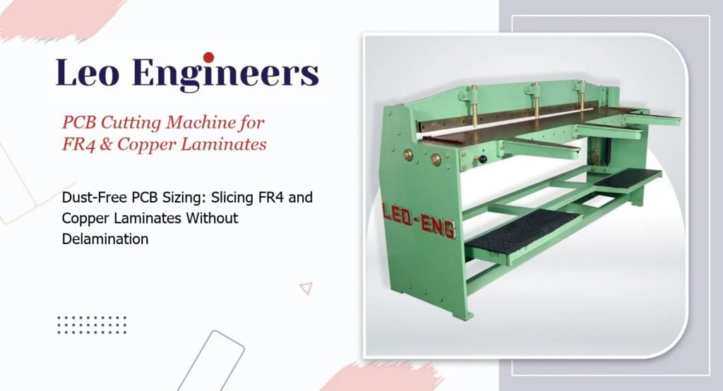
For information about the operating characteristics of industrial pneumatic cutting equipment, explore Leo Engineers’ Pneumatic Shearing Machine product range.
8. Controlling Dust and Debris During PCB Manufacturing
Contamination control is important in electronics production.
Fine particles generated during laminate processing can contaminate equipment, work surfaces and electronic assemblies.
For routing and sawing operations, appropriate dust-extraction systems should be used.
When evaluating alternative cutting methods, manufacturers should consider the complete process rather than assuming that eliminating a rotating cutting tool eliminates all contamination.
Mechanical cutting can still generate loose fibers and particulate debris.
Suitable housekeeping, inspection and cleaning procedures remain necessary.
9. Inspecting PCB Edges After Cutting
PCB cutting quality should be verified according to the board’s intended application and applicable manufacturing requirements.
A practical inspection process may include the following checks.| Inspection Area | What to Examine |
|---|---|
| Edge condition | Chipping, cracking and irregularities |
| Laminate integrity | Visible separation between material layers |
| Copper condition | Damage or lifting near the cutting edge |
| Dimensions | Compliance with specified measurements |
| Cleanliness | Loose fibers, chips and other debris |
| Board flatness | Unexpected bending or deformation |
10. Selecting a PCB Cutting Machine for EMS Production
Before purchasing cutting equipment, EMS providers should identify the materials and board designs they intend to process.
Important considerations include:
- PCB substrate material
- Board thickness
- Copper-layer configuration
- Cutting geometry
- Production volume
- Required dimensional tolerance
- Acceptable edge quality
- Dust and debris management
- Inspection requirements
Equipment selection should also consider whether the application involves unpopulated laminates, fabricated PCBs or assembled circuit boards.
These categories can require substantially different cutting and handling methods.
Conclusion
PCB cutting requires careful consideration of material construction, mechanical stress, edge quality and contamination control.
FR4, CEM-1 and copper-clad laminates do not necessarily respond identically to cutting forces.
While appropriately configured mechanical shearing may be suitable for selected straight-cutting applications, routing, sawing and other methods remain important for different PCB designs.
For electronics manufacturers and prototyping laboratories, the objective is to select a PCB Cutting Machine that meets the material, dimensional and quality requirements of the intended application.
Leo Engineers offers industrial cutting equipment. Contact the team to discuss your material-processing requirements and confirm whether a suitable machine configuration is available.